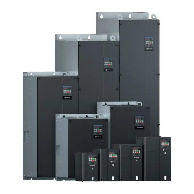
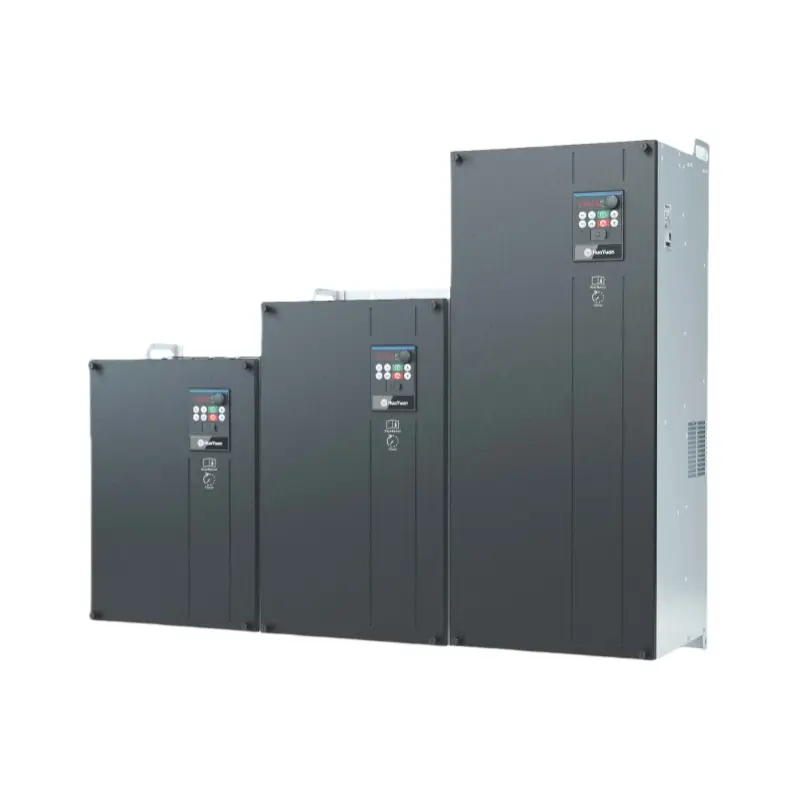
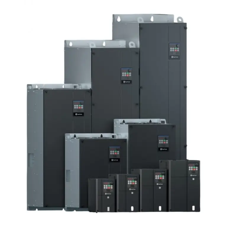
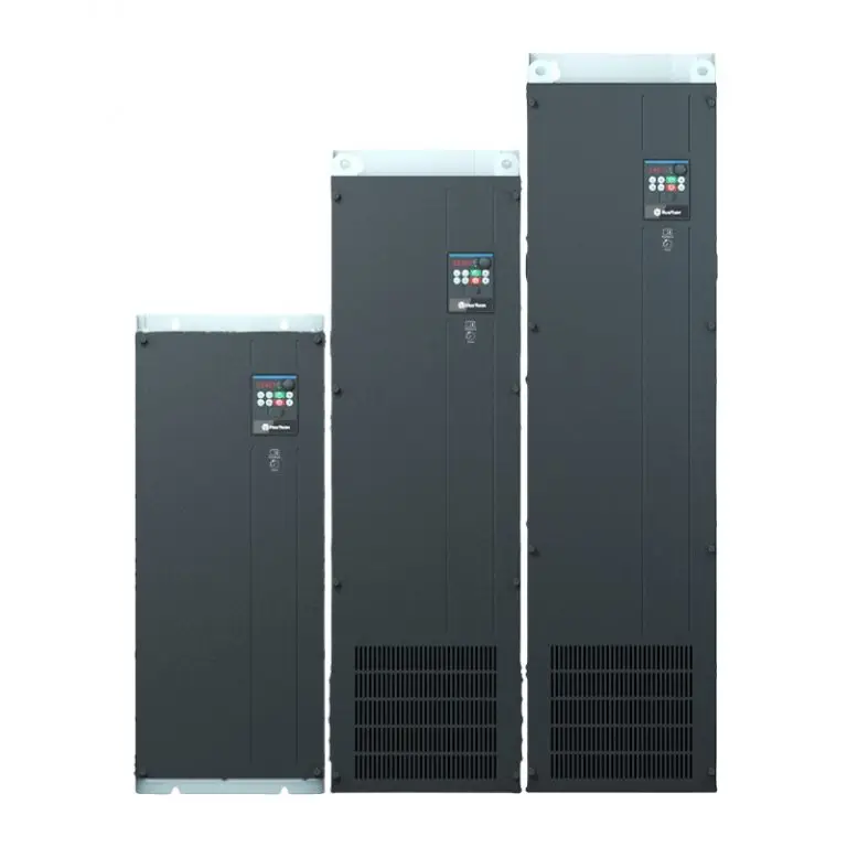
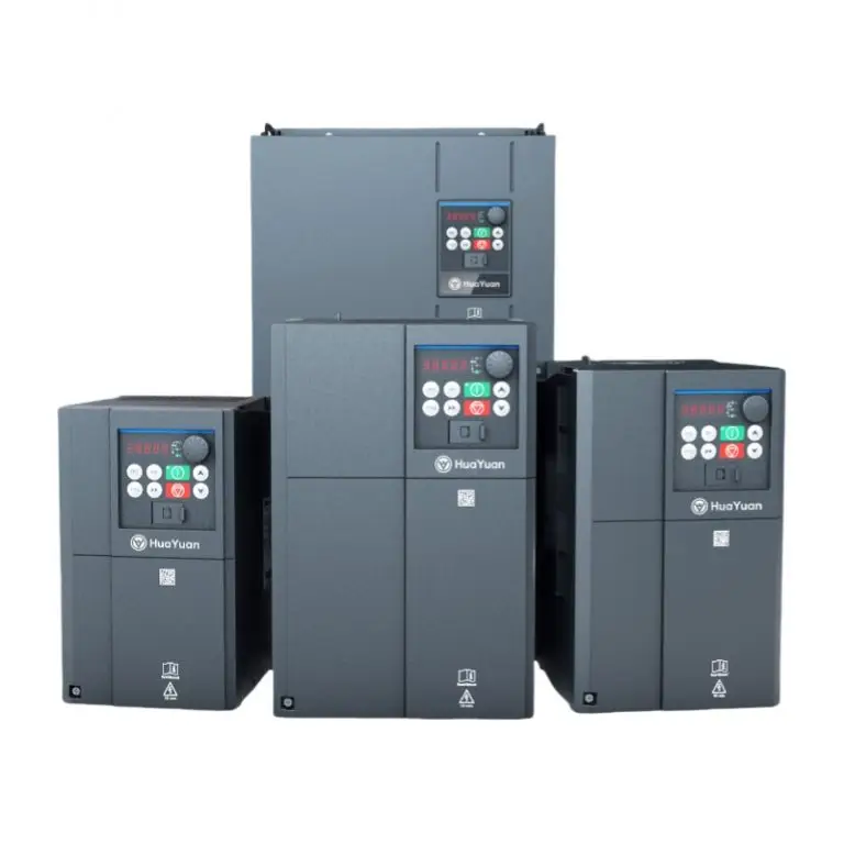
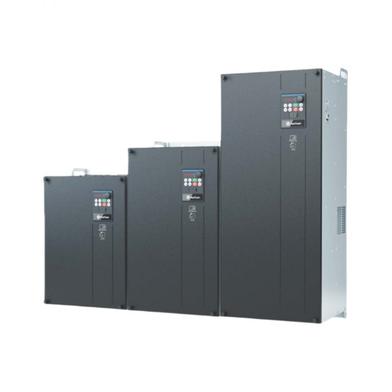
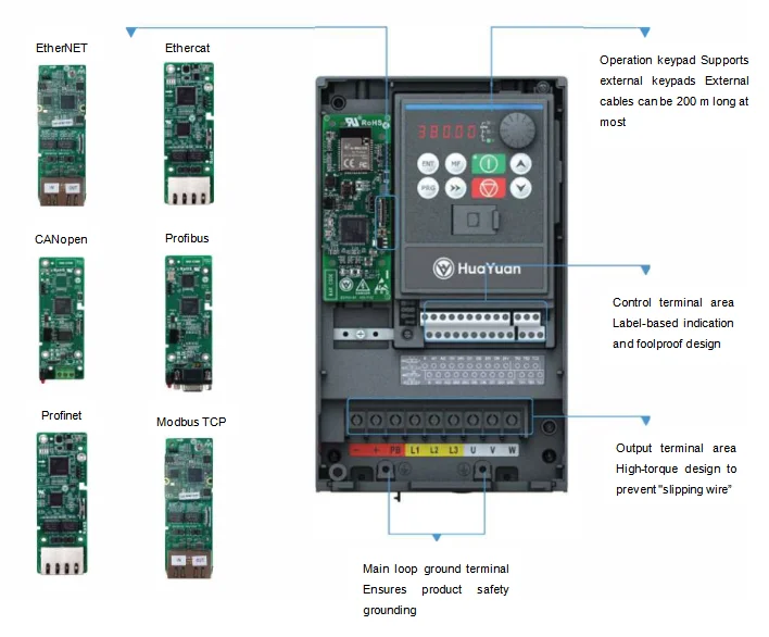
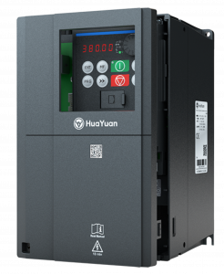
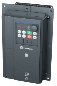
On the basis of inheriting the typical style of G1 series products, the G100 series general open-loop vector inverter is designed with appearance aesthetics and ergonomics in consideration in order to improve itspracticability, usability, and experience feelings, satisfying and even exceeding customers’ expectations.
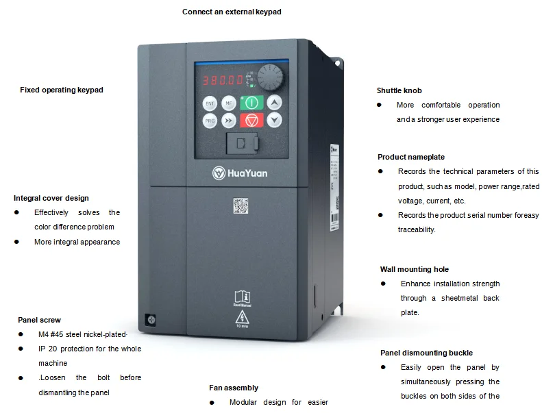
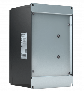
Diverse expansion interfaces, which supports a variety of l/O expansion cards, function expansion cards, and communication expansion cards, are needed in order to enhance product functionality and meet customers’different scenarios.
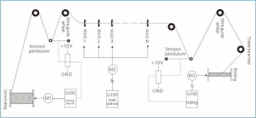
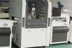
Schematic of a wire drawing machine with variable-frequency control, active paying-off, and constant tension take-up
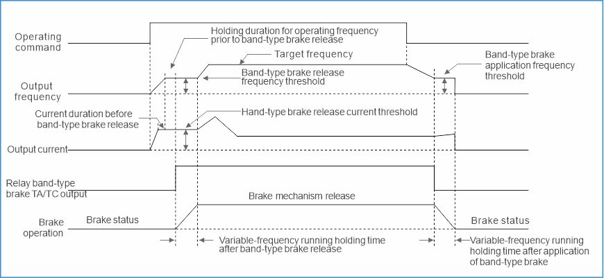
A logic timing diagram of a band-type brake
The logic parameter set of the brake meets the lifting industry’s application requirements.
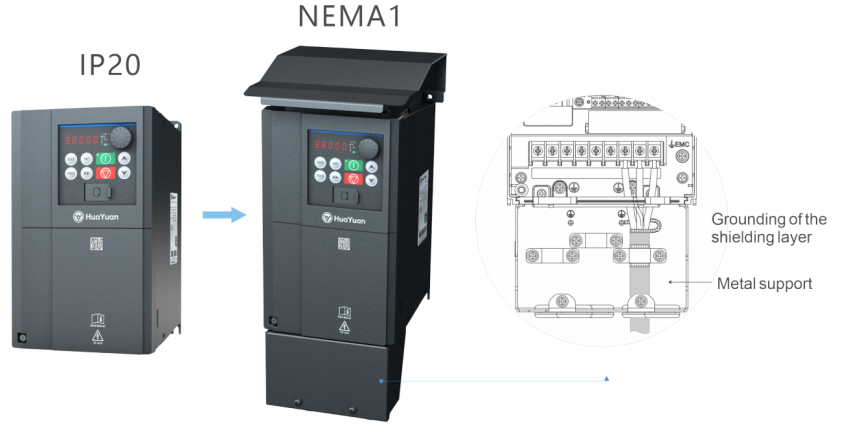
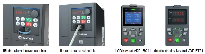
through panel mounting bracket
| Item | Specifications | ||
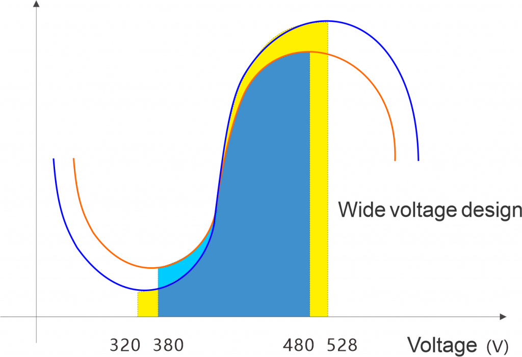
| Input | Rated voltage, frequency | 4T:380-480 V,50/60 Hz | |
| Allowable voltage fluctuating range | Fluctuating range: 320-528V; degree of unbalance: <3% Frequency range: 47-63Hz | ||
| Output | Output voltage | 0-INPUT | |
| Output frequency | 0-320 Hz | ||
| Overload capacity | N:150% – 60 s;180% – 3 s;200% – 0.5 s L:120% – 60s;130% – 3s;140% – 0.5s | ||
| Control feature | Control mode | V/F control, SVC | |
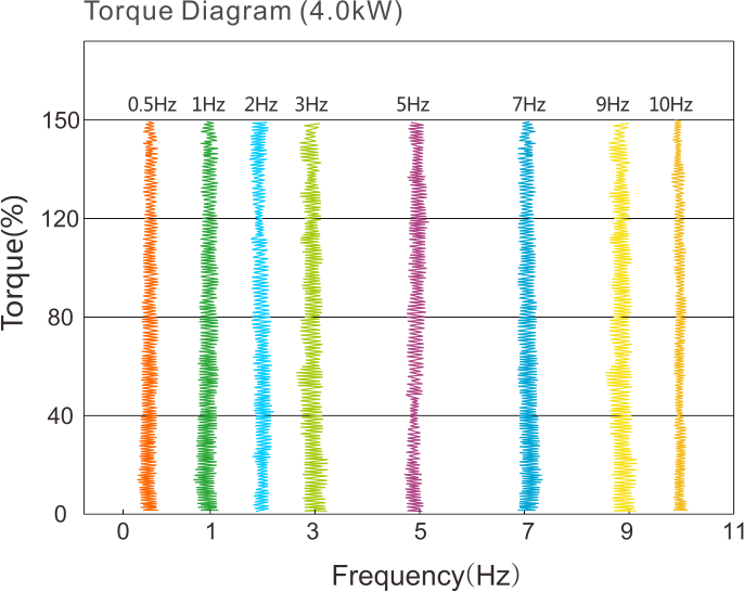
| Starting torque | 0.25Hz 150% (SVC) | ||
| Range of speed regulation | 1:100 (V/F);1:200 (SVC) | ||
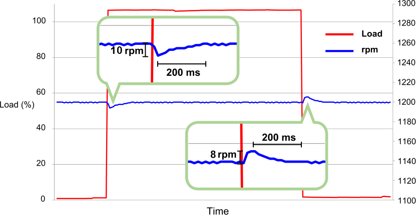
| Steady speed precision | ≤±0.5% (SVC) | ||
| Speed fluctuation | ≤±0.5% (SVC) | ||
| Torque control accuracy | SVC: ±5% (>=5.00Hz) | ||
| Torque response | ≤20ms (SVC) | ||
| Frequency precision | Low frequency operation mode | High frequency operation mode | |
| Digital setting: 0.01Hz Analog setting: maximum frequency ×0.2% | Digital setting: 0.1Hz Analog setting: maximum frequency ×0.2% | ||
| Frequency resolution | 0.01Hz | 0.1Hz | |
| Modulation system | SVPWM | ||
| Carrier frequency | 0.5 – 16kHz,modulated based on mode | ||
| Auto carrier adjustment | When the function is activated, the inverter can automatically adjust carrier frequency based on the temperature inside. | ||
| Torque boost | In V/F control mode, the torque can increase by 0.1% -30% manually. | ||
| Torque curve | 0: User customized V/F curve; 1: 2.0 power curve; 2: 1.7 power curve; 3: 1.2 power curve | ||
| Acceleration and deceleration time | 0-6500.0s, linear or sigmoid acceleration and deceleration curve mode, optional 4 groups of acceleration and deceleration time | ||
| Item | Specifications | |
| Basic functions | Inching functions | Jog frequency range: 0.00–maximum frequency |
| Jog acceleration/deceleration time: 0–6500.0 s | ||
| Simple PLC, multi speeds | Up to 16 speeds can be achieved through built-in PLC function and control terminal functions | |
| Internal PID | To achieve close-loop control | |
| Wakeup | Process PID has sleep and wakeup function | |
| Torque limit | The torque is limited during speed control to prevent frequent over-current alarm | |
| DC brake | Starting frequency: 0.00- the maximum set frequency | |
| Time: 0.01 – 30.00s (0.0: not activated) | ||
| Current: 0.0-100.0% inverter rated current | ||
| Auto voltage regulation (AVR) | When input voltage deviates from the rated value, the function can be used to keep output voltage constant, so AVR is activated in general, especially when input voltage is higher than the rated value | |
| Auto current-limiting | When the input voltage deviates from the rated voltage, the function can be used to regulate the output voltage, so that AVR should be activated under normal circumstance, especially when the input voltage is higher than the rated voltage | |
| Over-voltage stalling control | Used to control the voltage of DC bus during the running of the inverter to prevent overvoltage of DC bus | |
| MODBUS communication | Standard MODBUS communication protocol for rapid communication with peripherals | |
| Special functions | Binding function | Operation command channel is bound with power input channel, without parameter setting |
| Input terminal drain/source section | Through jumper terminal, drain or source can be chosen for DI1- DI7 to meet the needs in different cases | |
| Multi AI curve correction | Up to 4 points can be chosen to set AI curve for flexible and convenient curve correction | |
| Double motor parameters | Two sets of parameters of asynchronous inverters are stored to achieve the switching function between two different motors | |
| Virtual I / O port | 5 virtual DI/DO ports make complex logic control applications convenient | |
| Customer-defined parameter set | The customer can choose the required parameter set, sent to P17 as the custom parameter for daily view and modification | |
| Item | Specifications | |
| Operation and running | Command source channel | Three modes, keyboard setting, external terminal setting, communication setting, switchable |
| Frequency source channel | Digital setting, analog setting, pulse setting, multi-speed, communication setting etc. for selection | |
| Input terminal | 7 digital input terminals, DI1-DI7, drain and source input can be chosen DI7 can be used as a high speed pulse input, supporting 12 V and 24 V level, the maximum frequency of 100 KHz | |
| 2 analog input terminals AI1:0 – 10V or 0-20 mA can be chosen: AI2:0 – 10V can be chosen through parameter setting, 2 analog input terminals AI both can be used as digital input terminal DI | ||
| Output terminal | 1 group programmable switch output, the output level is 24 V when open | |
| 2 group programmable relay output, 250 VAC/3 A 30VDC/ 3A | ||
| 2 group analog output terminals, 0-10 V or 0-20 mA can be chosen | ||
| Modle | Size | Braking unit | DC resistor | Rated output voltage (VAC) | Normal Duty | Light Duty | ||||
| Rated output current(A) | Rated input capacity (kVA) | Motor type (kW) | Rated output current(A) | Rated input capacity (kVA) | Motor type (kW) | |||||
| G100-4T00401N/00551L-A | A | Built-in | / | 380 | 10 | 5.9 | 4 | 13 | 8.6 | 5.5 |
| G100-4T00551N/00751L-A | A | Built-in | / | 380 | 13 | 8.6 | 5.5 | 17 | 11.2 | 7.5 |
| G100-4T00751N/01102L-B | B | Built-in | / | 380 | 17 | 11.2 | 7.5 | 25 | 16.5 | 11 |
| G100-4T01102N/01502L-B | B | Built-in | / | 380 | 25 | 16.5 | 11 | 32 | 21 | 15 |
| G100-4T01502N/01852L-C | C | Built-in | / | 380 | 32 | 21 | 15 | 38 | 25 | 18.5 |
| G100-4T01852N/02202L-C | C | Built-in | / | 380 | 38 | 25 | 18.5 | 45 | 30 | 22 |
| G100-4T02202N/03002L-C | C | Built-in | / | 380 | 45 | 30 | 22 | 60 | 40 | 30 |
| G100-4T03002N/03702L-D | D | / | / | 380 | 60 | 40 | 30 | 75 | 50 | 37 |
| G100-4T03002N/03702L-D-B | D | Optional built-in | / | 380 | 60 | 40 | 30 | 75 | 50 | 37 |
| G100-4T03702N/04502L-D | D | / | / | 380 | 75 | 50 | 37 | 90 | 60 | 45 |
| G100-4T03702N/04502L-D-B | D | Optional built-in | / | 380 | 75 | 50 | 37 | 90 | 60 | 45 |
| G100-4T04502N/05502L-E | E | / | / | 380 | 90 | 60 | 45 | 110 | 75 | 55 |
| G100-4T04502N/05502L-E-B | E | Optional built-in | / | 380 | 90 | 60 | 45 | 110 | 75 | 55 |
| G100-4T04502N/05502L-E-DCL | E | / | Optional built-in | 380 | 90 | 60 | 45 | 110 | 75 | 55 |
| G100-4T05502N/07502L-E | E | / | / | 380 | 110 | 75 | 55 | 150 | 99 | 75 |
| G100-4T05502N/07502L-E-B | E | Optional built-in | / | 380 | 110 | 75 | 55 | 150 | 99 | 75 |
| G100-4T05502N/07502L-E-DCL | E | / | Optional built-in | 380 | 110 | 75 | 55 | 176 | 99 | 75 |
| G100-4T07502N/09002L-E | E | / | / | 380 | 150 | 99 | 75 | 176 | 116 | 90 |
| G100-4T07502N/09002L-E-B | E | Optional built-in | / | 380 | 150 | 99 | 75 | 176 | 116 | 90 |
| G100-4T07502N/09002L-E-DCL | E | / | Optional built-in | 380 | 150 | 99 | 75 | 210 | 116 | 90 |
| G100-4T09002N/11003L-F | F | / | / | 380 | 176 | 116 | 90 | 210 | 139 | 110 |
| G100-4T09002N/11003L-F-B | F | Optional built-in | / | 380 | 176 | 116 | 90 | 210 | 139 | 110 |
| Modle | Size | Braking unit | DC resistor | Rated output voltage (VAC) | Normal Duty | Light Duty | ||||
| Rated output current(A) | Rated input capacity (kVA) | Motor type (kW) | Rated output current(A) | Rated input capacity (kVA) | Motor type (kW) | |||||
| G100-4T09002N/11003L-F-DCL | F | / | Optional built-in | 380 | 176 | 116 | 90 | 210 | 139 | 110 |
| G100-4T11003N/13203L-F | F | / | / | 380 | 210 | 139 | 110 | 250 | 164 | 132 |
| G100-4T11003N/13203L-F-B | F | Optional built-in | / | 380 | 210 | 139 | 110 | 250 | 164 | 132 |
| G100-4T11003N/13203L-F-DCL | F | / | Optional built-in | 380 | 210 | 139 | 110 | 250 | 164 | 132 |
| G100-4T13203N/16003L-G | G | / | / | 380 | 250 | 164 | 132 | 300 | 197 | 160 |
| G100-4T13203N/16003L-G-DCL | G | / | Optional built-in | 380 | 250 | 164 | 132 | 300 | 197 | 160 |
| G100-4T16003N/18503L-G | G | / | / | 380 | 300 | 197 | 160 | 340 | 224 | 185 |
| G100-4T16003N/18503L-G-DCL | G | / | Optional built-in | 380 | 300 | 197 | 160 | 340 | 224 | 185 |
| G100-4T18503N/20003L-H | H | / | Built-in | 380 | 340 | 224 | 185 | 380 | 250 | 200 |
| G100-4T20003N/22003L-H | H | / | Built-in | 380 | 380 | 250 | 200 | 415 | 273 | 220 |
| G100-4T22003N/25003L-H | H | / | Built-in | 380 | 415 | 273 | 220 | 470 | 309 | 250 |
| G100-4T25003N/28003L-H | H | / | Built-in | 380 | 470 | 309 | 250 | 520 | 342 | 280 |
| G100-4T28003N/31503L-J | J | / | Built-in | 380 | 520 | 342 | 280 | 600 | 395 | 315 |
| G100-4T31503N/35003L-J | J | / | Built-in | 380 | 600 | 395 | 315 | 650 | 421 | 350 |
| G100-4T35003N/40003L-J | J | / | Built-in | 380 | 650 | 421 | 350 | 720 | 454 | 400 |
| G100-4T40003N/45003L-J | J | / | Built-in | 380 | 720 | 454 | 400 | 810 | 530 | 450 |
| G100-4T50003N-K | K | / | Built-in | 380 | 720 | 454 | 400 | / | / | / |
| G100-4T63003N-K | K | / | Built-in | 380 | 940 | 618 | 500 | / | / | / |
| G100-4T80003N-K | K | / | Built-in | 380 | 1200 | 790 | 630 | / | / | / |
| *G100-4T04502N/05502L-D | D | / | / | 380 | 90 | 60 | 45 | 110 | 75 | 55 |
| *G100-4T04502N/05502L-D-B | D | Optional built-in | / | 380 | 90 | 60 | 45 | 110 | 75 | 55 |
Tips: Models with * are suitable for specific occasions, please consult customer service for specific information
| OPTIONAL ACCESSORIES | ||||||||
| Size | Installation Method | Optional Accessories | ||||||
| Wall-mounting Type | Flush-mounting Type | Floor-standing Type | Flush-mounting Kit | NEMA1 Protective Accessory Kit | Shielded Cable Grounding Kit | Dust-proof Accessory Kit | Base | |
| A | √ | √ | / | √ | √ | √ | √ | / |
| B | √ | √ | / | √ | √ | √ | √ | / |
| C | √ | √ | / | √ | √ | √ | √ | / |
| D | √ | √ | / | √ | √ | √ | √ | / |
| E | √ | √ | / | √ | / | / | √ | / |
| F | √ | √ | / | √ | / | / | √ | / |
| G | √ | √ | / | √ | / | / | √ | / |
| H | √ | / | √ | / | √ | / | / | √ |
| J | √ | / | √ | / | √ | / | / | √ |
| K | / | / | √ | / | / | / | / | / |
| Name | Model | Description | Notes |
| Communication Card | EG100TX11 | CANopen Communication Card | Configuration files for the G100 and G100E series are independent and non-interchangeable. Only one function card (communication, I/O expansion, or temperature detection) can be supported on a single device at the same time; the three cannot be used simultaneously. |
| EG100TX31 | EtherCAT Communication Card | ||
| EG100TX51 | EtherNet/IP Communication Card | ||
| EG100TX61 | Modbus TCP/IP Communication Card | ||
| EG100TX21 | PROFIBUS Communication Card | ||
| EG100TX41 | PROFINET Communication Card | ||
| I/O Expansion Card | EG100IO11 | I/O Expansion Card: 4 DI, 2 AI (0~10V/0~20mA), 4 DO (Open-collector output), 2 NO/NC Relay | / |
| Temperature Detection Card | EG100PT11 | Supports 2 PT100 | Only available for the G100E series |
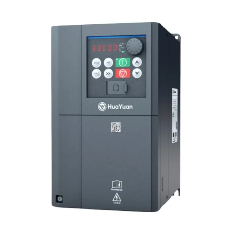
| Keypad | VDP-BT22 | Dual-Display Keypad, External Cable Distance 200m | / |
| VDP-SE12 | Single-Display Keypad, External Cable Distance 200m | / | |
| VDP-BC42 | LCD keypad, supporting Wi-Fi and Bluetooth functions | / |